ELECHOUSE RFID Serial Config Product Test Guide
This guide describes how to test the current V0.1H main control + HF product with the browser-based rfid-serial-config page. It covers Web Serial connection, device status reading, WiFi setup, USB CDC command interaction, UART output configuration, and HF function checks.
1. Test Scope
This document covers tests that can be performed directly from the Serial Config page: Web Serial connection, status reading, WiFi parameter setup, USB CDC command interaction, product UART interface setup, reader output setup, HF scan mode, and the HF card emulation configuration entry.
2. Test Environment
YOU. The password is recorded as B********7.3. Connect COM3
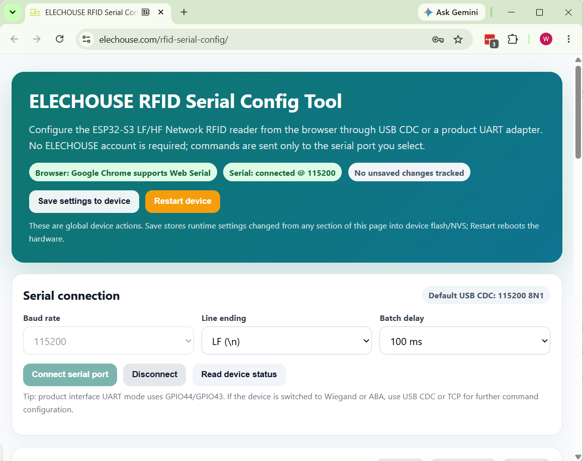
- Open
https://www.elechouse.com/rfid-serial-config/. - Confirm that the top status area shows
Browser: Google Chrome supports Web Serial. - Click
Connect serial port. - Select
COM3in the browser serial port picker and confirm the connection. - The top status area should show
Serial: connected @ 115200.
4. Read Device Status
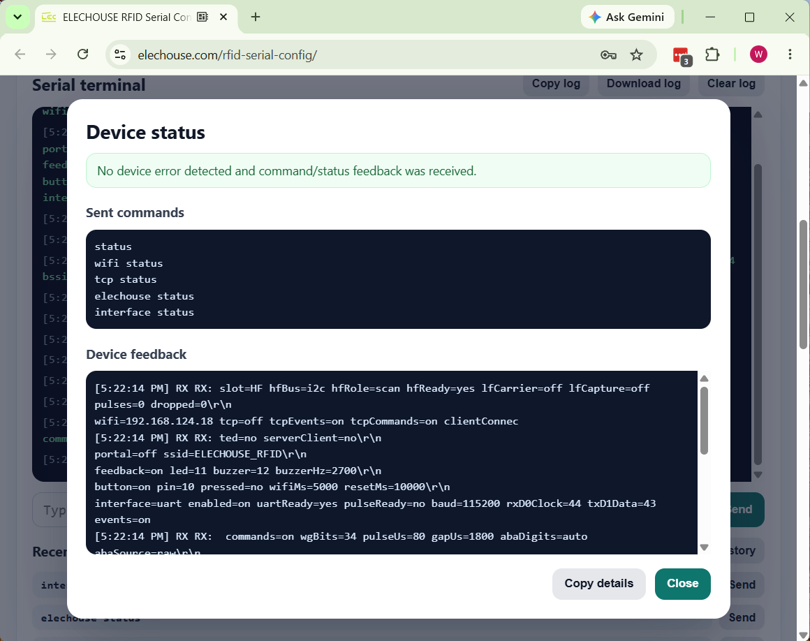
- Click
Read device status. - The page sends
status,wifi status,tcp status,elechouse status, andinterface status. - Check that the result dialog reports no device error, then review the Device feedback content.
slot=HF hfBus=i2c hfRole=scan hfReady=yes
wifi ssid=YOU passLen=9 hostname=ELECHOUSE_RFID status=CONNECTED(3) ip=192.168.124.18 rssi=-54
tcp mode=off listen=9000 events=on commands=on
interface mode=uart enabled=yes uartReady=yes d0Clock=44 d1Data=43 events=on commands=on baud=115200
5. WiFi Configuration
- Enter
YOUin the SSID field. - Enter the WiFi password in the Password field. Record the password in masked form in documentation.
- Click
Send WiFi settings. The page sendswifi set <ssid> <password>. - Click
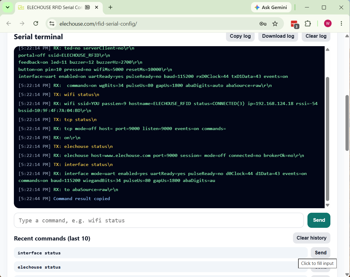
wifi statusor runRead device statusagain to verify the connection.
YOU and the device IP address is 192.168.124.18.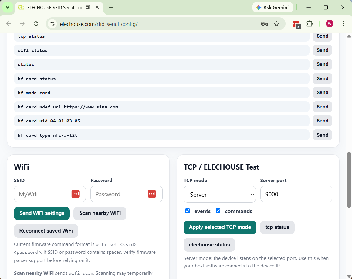
6. Command Test
The Serial Terminal can send standard configuration commands directly to the device. The default line ending is LF, which matches the current firmware command parser.
| Test Item | Command | Expected Result |
|---|---|---|
| Device status | status |
Returns slot, HF/LF, WiFi, TCP, interface, feedback, and other device status fields. |
| WiFi status | wifi status |
Returns SSID, connection state, IP address, and RSSI. |
| Interface status | interface status |
Returns the active UART/Wiegand/ABA mode and output parameters. |
| HF status | hf status |
Returns HF mode, ready state, and polling technology settings. |
7. UART Output Configuration
V0.1H currently uses UART as the primary product data output interface. For this test, keep UART enabled, events enabled, and UART commands enabled.
| Parameter | Measured Value | Description |
|---|---|---|
| Mode | UART |
The product interface outputs data through UART. |
| UART baud | 115200 |
Matches the default USB CDC test baud rate. |
| GPIO | rxD0Clock=44, txD1Data=43 |
Current hardware interface assignment. |
| events / commands | on / on |
Allows event output and also allows commands to be sent through UART. |
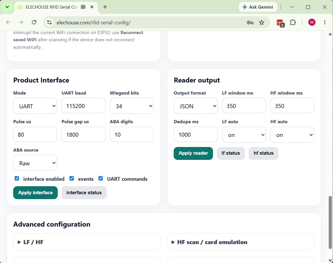
8. Reader Output Configuration
Reader output controls the card event format, duplicate suppression window, and LF/HF automatic reading switches.
| Parameter | Recommended Test Value | Purpose |
|---|---|---|
| Output format | JSON |
Easy for host software to parse card events. |
| LF/HF window | 350 ms / 350 ms |
Card read window duration. |
| Dedupe | 1000 ms |
Suppresses repeated output for the same card. |
| HF auto | on |
Required for V0.1H HF card reading tests. |
9. HF Reading and Card Emulation
HF card reading test
- Confirm that HF mode is set to
Scan. - Confirm that
ISO14443Ais enabled. Enable ISO14443B, NFC-F, or ISO15693 only when those card types need to be tested. - Place an HF card on the antenna area.
- Watch the Serial Terminal for an HF card event or UID output.
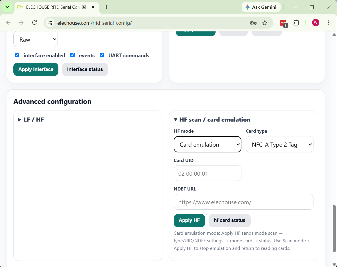
hfBus=i2c, hfRole=scan, and hfReady=yes, so HF scanning is ready.HF card emulation configuration
- Expand
HF scan / card emulationin Advanced configuration. - Set HF mode to
Card emulation. - Select a card type, such as
NFC-A Type 2 TagorNFC-A Type 4 Tag. - Enter the Card UID and NDEF URL.
- Click
Apply HF, then read the emulated card with an NFC-enabled phone. - The expected phone-side result is the configured NDEF URL or a tag record matching the configured UID/card type.
10. Save and Reboot
- After confirming the settings, click
Save settings to deviceat the top of the page. - To verify persistence, click
Restart deviceor power-cycle the device manually. - After reboot, reconnect COM3 and run
Read device status. - Confirm that WiFi, interface, reader output, and HF mode settings remain as expected.
11. Troubleshooting
| Symptom | Possible Cause | Action |
|---|---|---|
| The browser does not show the COM list | The browser does not support Web Serial, or the click was not a real user gesture. | Use desktop Chrome or Edge on Windows and click Connect serial port manually. |
| COM3 cannot be opened | The serial port is occupied by another tool. | Close serial terminals, flashing tools, or other browser pages that may be using COM3. |
| No response after sending commands | Incorrect baud rate or line ending. | Use 115200 8N1 and set Line ending to LF. |
| WiFi does not connect after setup | Wrong SSID/password or weak signal. | Run wifi status and check status, IP address, and RSSI. |
| No output after placing an HF card | HF is not initialized, the device is not in Scan mode, or the card type is unsupported. | Run hf status and confirm hfReady=yes and ISO14443A is enabled. |
| The phone cannot read card emulation | NFC is disabled on the phone, card type/UID settings are not suitable, or the device has not entered card mode. | Run hf card status and confirm role=card and active=yes. |
12. Test Record
| Test Item | Result | Record |
|---|---|---|
| Chrome Web Serial connection to COM3 | PASS | The page showed Serial connected @ 115200. |
| Read device status | PASS | All status commands returned without a device error. |
| WiFi status | PASS | SSID is YOU, status is CONNECTED, IP is 192.168.124.18. |
| UART interface | PASS | UART enabled, baud 115200, events/commands on. |
| HF scan ready | PASS | hfRole=scan and hfReady=yes. |
| HF card emulation configuration entry | PASS | The page can switch to Card emulation and shows card type, UID, and NDEF URL settings. |