ELECHOUSE Network RFID Reader V0.1H is a development kit, not a finished access-control reader. It is intended for HF RFID/NFC function evaluation, firmware development, network data upload testing, and hardware interface planning before a production version is finalized.
Product stage
V0.1H development kit
Current module set
Main controller + HF
Current RF target
13.56 MHz HF/NFC
Scope note: LF 125 kHz, dual-frequency operation, BLE, 12V input, PoE, external WiFi antenna, and productized Wiegand/ABA electrical interfaces are roadmap items or experimental directions. They are not part of the V0.1H formal hardware specification.
2. Key Features
Category
V0.1H Status
Notes
HF RFID/NFC ID reading
Current
HF card UID/ID reading through the ST25R3916B front end.
HF card emulation
Current
NFC-A Type 2 Tag and Type 4 Tag emulation modes with configurable UID and NDEF payloads.
WiFi configuration
Current
2.4 GHz WiFi station configuration through command line, portal, or Web Serial tool.
Command configuration
Current
Commands are available through USB CDC, product UART, and TCP when enabled.
UART data output
Current
3.3V TTL UART on GPIO44/GPIO43. No 5V to 3.3V level conversion is fitted in V0.1H.
TCP data output
Current
TCP client, TCP server, and ELECHOUSE online Broker test mode.
Buzzer feedback
Current
On-board buzzer for local read/configuration feedback.
Button
Current
On-board button available for configuration and reset workflows.
LED indicator
Not fitted
No LED is populated on V0.1H. LED status feedback is planned for a later hardware revision.
Wiegand/ABA output
Firmware capable
Can be mapped to GPIO44/GPIO43 in firmware, but productized electrical interface is planned for V0.2H.
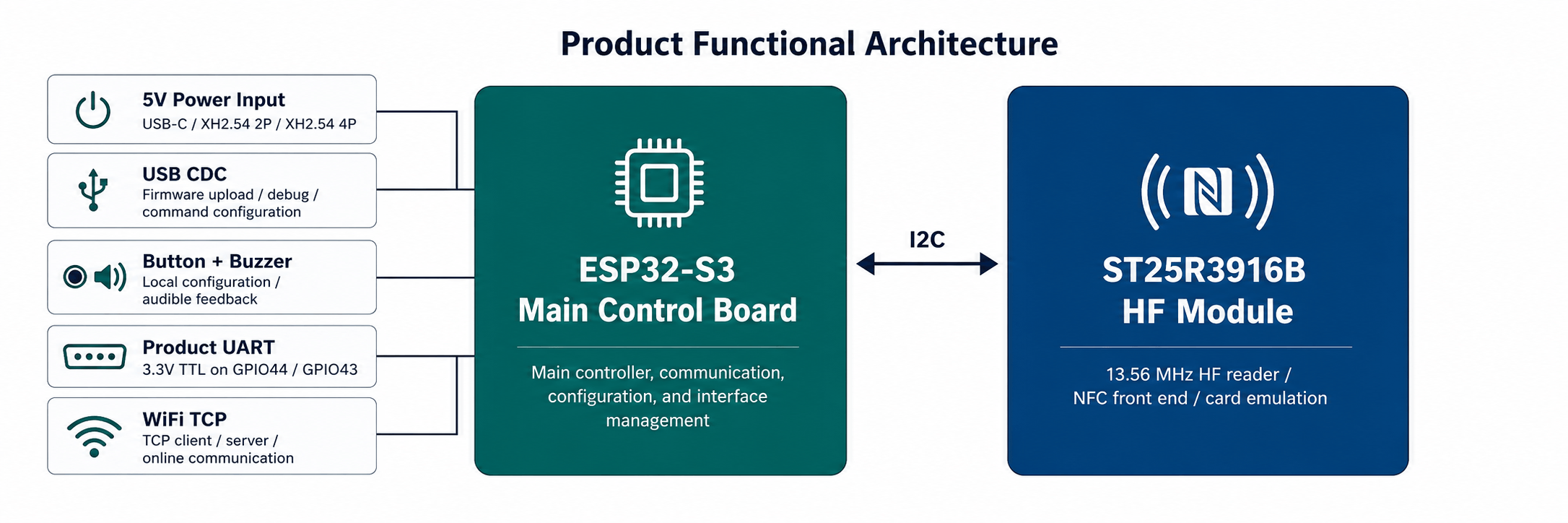
3. System Architecture
Product functional architecture: 5V power input, USB CDC, button and buzzer, product UART, WiFi TCP, ESP32-S3 main control board, and ST25R3916B HF module over I2C.
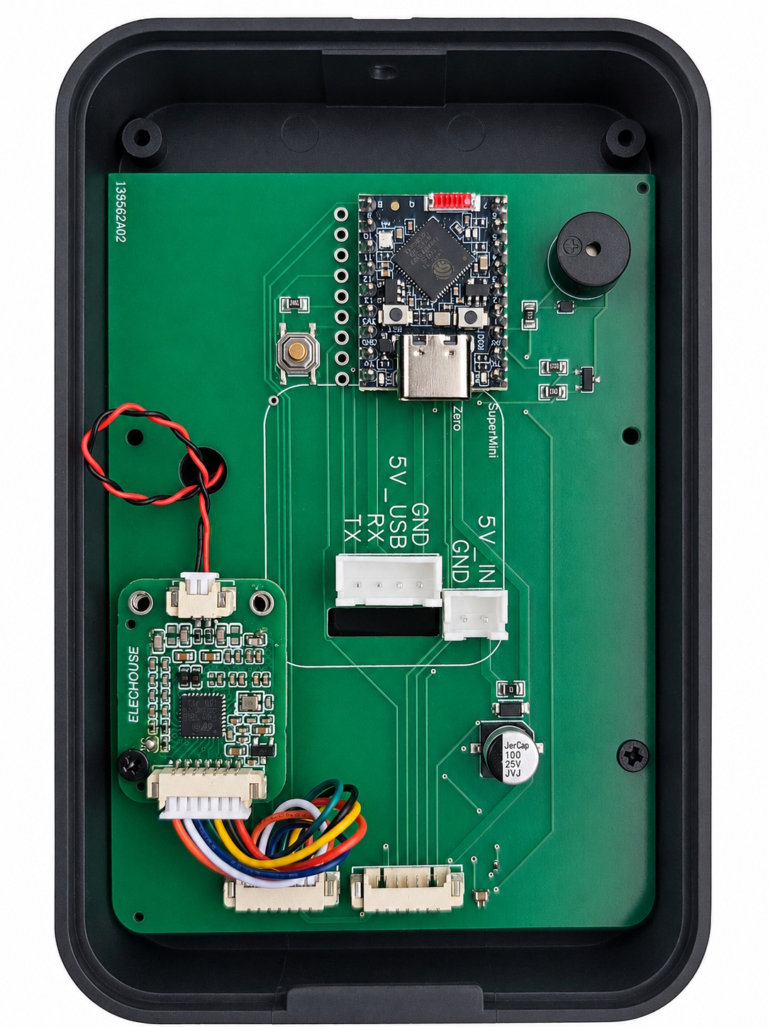
4. Hardware Overview
ESP32-S3 controller
USB-C: power, upload, USB CDC
Configuration button
ST25R3916B HF module
On-board buzzer
Product UART: TX, RX, 5V_USB, GND
5V_IN and GND power input
V0.1H internal layout reference. This prototype has button and buzzer populated, but no LED indicator and no UART level-shift/protection circuit.
Item
V0.1H Specification
Main controller
ESP32-S3 module
Wireless
2.4 GHz WiFi. BLE is planned, not enabled as a V0.1H product feature.
HF front end
ST25R3916B, 13.56 MHz
HF bus
I2C by default: SCL GPIO5, SDA GPIO7, IRQ GPIO9
Power
5V DC input through USB-C connector, XH2.54 2P cable, or XH2.54 4P cable. 12V and PoE are not supported in V0.1H.
Feedback
Buzzer populated. LED not populated.
Configuration control
Button on GPIO10, active-low
Product interface
UART on GPIO44/GPIO43, 3.3V TTL logic
Electrical caution: ESP32-S3 GPIO is 3.3V logic and is not 5V tolerant. Do not connect 5V controller signals directly to UART, Wiegand, ABA, or other GPIO pins on V0.1H.
5. Electrical Characteristics
Parameter
Value
Notes
Input voltage
5V DC
V0.1H does not support direct 12V input or PoE power input.
Rated current
0.19A
Measured during normal powered operation.
Rated power
0.95W
Calculated from 5V x 0.19A.
Standby current
0.08A
Standby state, not a low-power MCU mode.
Standby power
0.40W
Calculated from 5V x 0.08A.
Power input methods
USB-C connector, XH2.54 2P cable, XH2.54 4P cable
Use only one 5V supply path at a time unless the test setup is explicitly designed for shared power.
GPIO logic level
3.3V
ESP32-S3 GPIO is not 5V tolerant.
Standby wording: The standby current and standby power values describe a low-activity standby condition. They should not be interpreted as a low-power MCU mode consumption value.
6. Connector and Pin Reference
Interface
Signals
Electrical Note
V0.1H Use
USB-C on ESP32-S3
USB data, 5V power
Physical USB-C connector. Provides USB CDC serial, firmware upload, and debug power.
Recommended development interface
5V power connector
5V_IN, GND
XH2.54 2P, 5V only
External 5V supply input
Product UART connector
TX, RX, 5V_USB, GND
XH2.54 4P. GPIO44/GPIO43, 3.3V TTL. No 5V level conversion.
Product data output and command input
HF module connection
I2C SCL/SDA, IRQ, 5V, GND
Internal module connection
ST25R3916B HF RFID/NFC operation
Button
GPIO10 active-low
Board-level user/config input
Configuration portal and reset workflow support
Buzzer
GPIO12
On-board audible feedback
Read/configuration feedback
Default GPIO Mapping
Function
GPIO
Status
HF SCL
GPIO5
Current I2C bus
HF SDA
GPIO7
Current I2C bus
HF IRQ
GPIO9
Current interrupt input
Button
GPIO10
Current, active-low
Buzzer
GPIO12
Current
Product UART RX
GPIO44
Current, 3.3V TTL
Product UART TX
GPIO43
Current, 3.3V TTL
LED data
GPIO11 in firmware profile
Not populated on V0.1H hardware
7. Software and Firmware Features
HF RFID/NFC
HF UID/ID reading through ST25R3916B.
NFC-A Type 2 Tag and Type 4 Tag card emulation modes.
Configurable emulation UID.
NDEF payload support for URL, text, vCard, and WiFi records.
Configuration Interfaces
USB CDC serial command configuration.
Product UART command configuration when enabled.
TCP command configuration when TCP commands are enabled.
WiFi configuration portal.
Web Serial configuration through the ELECHOUSE Serial Config Tool.
Data Output
UART event output, default 115200 8N1.
TCP Client mode for connecting to a LAN or cloud service.
Actual card type and ID fields depend on the card technology, reader mode, and enabled output format.
Core Command Groups
Group
Examples
Purpose
System
status, pins, save, reboot
Inspect device state and persist configuration.
WiFi
wifi status, wifi set <ssid> <password>
Configure station WiFi credentials.
TCP
tcp client <host> <port>, tcp server <port>, tcp off
Configure network data transport.
ELECHOUSE Broker
elechouse on <session_code>, elechouse status, elechouse off
Connect to the online Broker test page.
HF
hf mode scan, hf mode card, hf card type nfc-a-t2t
Configure HF scanning or card emulation.
8. Wiegand/ABA Evaluation
The firmware can reuse the current product interface pins, GPIO44 and GPIO43, as two-wire pulse outputs for Wiegand D0/D1 or ABA Clock/Data. This is practical at firmware level because UART TX/RX are general ESP32-S3 GPIO pins.
V0.1H decision: Wiegand/ABA should not be described as a production-ready electrical interface for this hardware revision. V0.1H has no 5V to 3.3V conversion, no open-drain output stage, and no ESD/surge protection on the product interface.
Question
Assessment
Can GPIO44/GPIO43 implement Wiegand or ABA in firmware?
Yes. They can be switched from UART to pulse output mode by firmware.
Can V0.1H connect directly to a typical 5V access controller?
No. Direct connection is not recommended because ESP32-S3 GPIO is 3.3V only and not 5V tolerant.
Can it be used for lab evaluation?
Only with a 3.3V-compatible receiver, common ground, short wiring, and controlled test conditions.
What should V0.2H add?
Level conversion or open-drain drivers, pull-up strategy, ESD/surge protection, connector labeling, and validation with real access controllers.
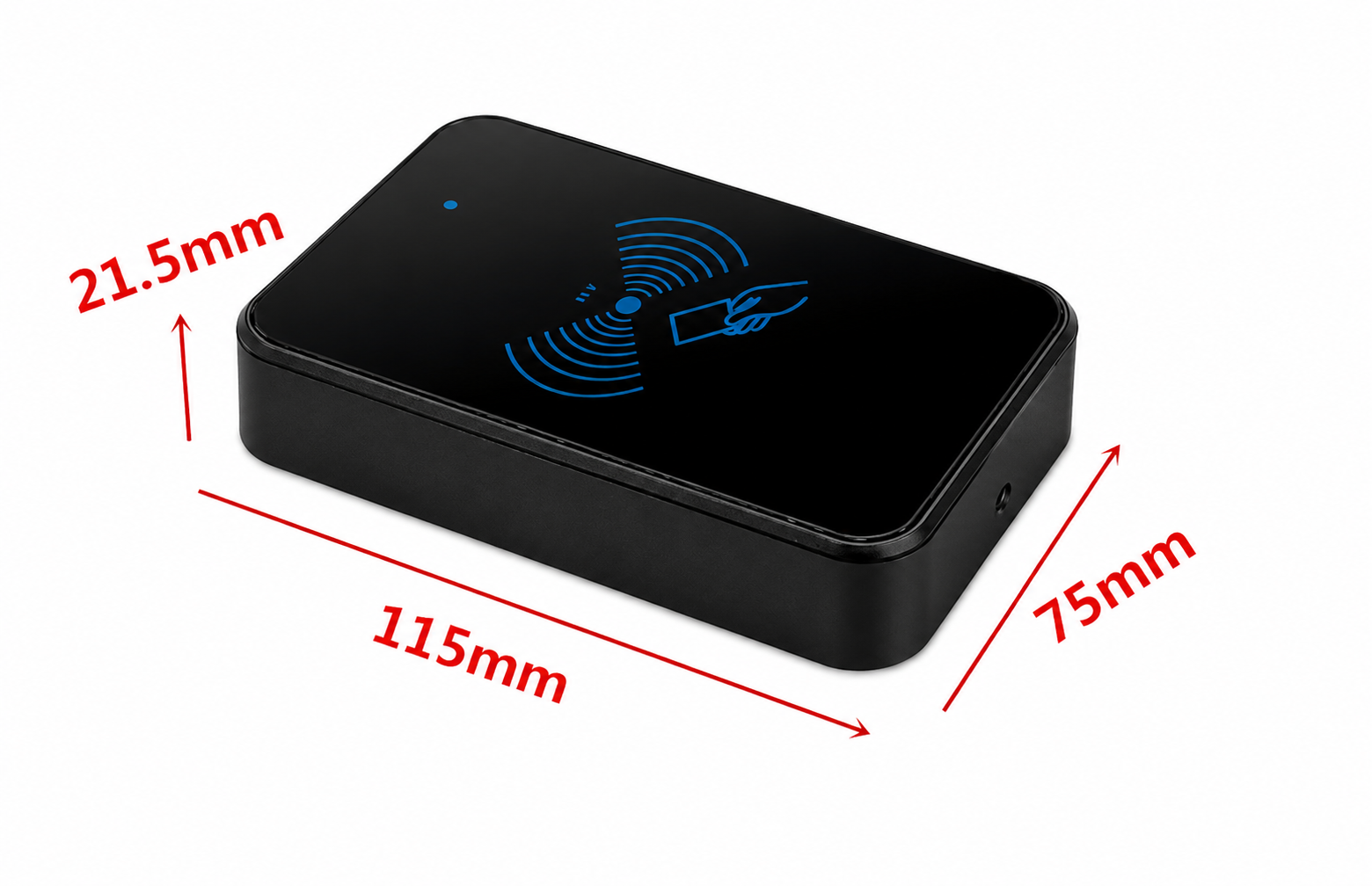
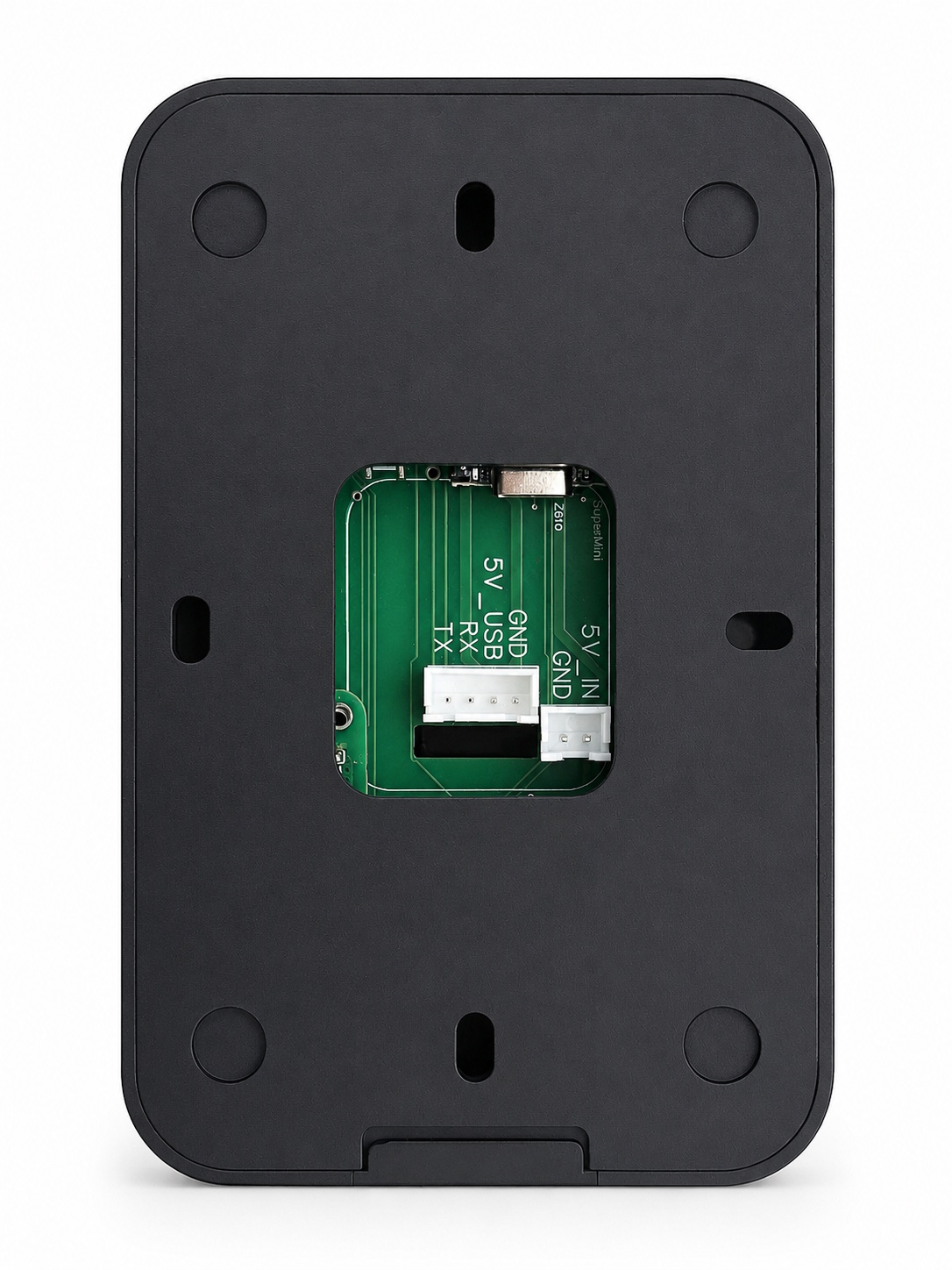
9. Mechanical Reference
Reference enclosure dimensions: 115 mm x 75 mm x 21.5 mm.Rear mounting plate and cable window reference for installation planning.
Publishing note: These local file links work when the datasheet is opened from this documentation package. When publishing to the website, upload the linked resources to fixed web paths and replace the relative links with public URLs.