PN7160 MINI V1 -- I2C
ESP32-S3 quick start
Connect the module, adapt the official ELECHOUSE DetectTags example to your pins and supply, then check NFC-A tag detection.
1. What you need
- PN7160 MINI V1 module and one of its included 50 × 40 mm or 25 × 10 mm antennas.
- ESP32-S3 SuperMini, a USB data cable and Arduino IDE with the Espressif ESP32 board package.
- A compatible 1.25 mm six-pin host cable or wiring harness, purchased separately.
- An NFC-A tag, such as a MIFARE card, for the first check.
The six-pin host cable and development board are not included. A 100 × 160 mm antenna is available separately; see the datasheet for package contents and reading-distance references.
2. Connect the module
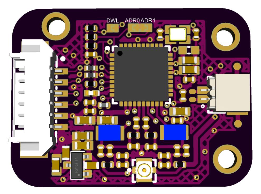
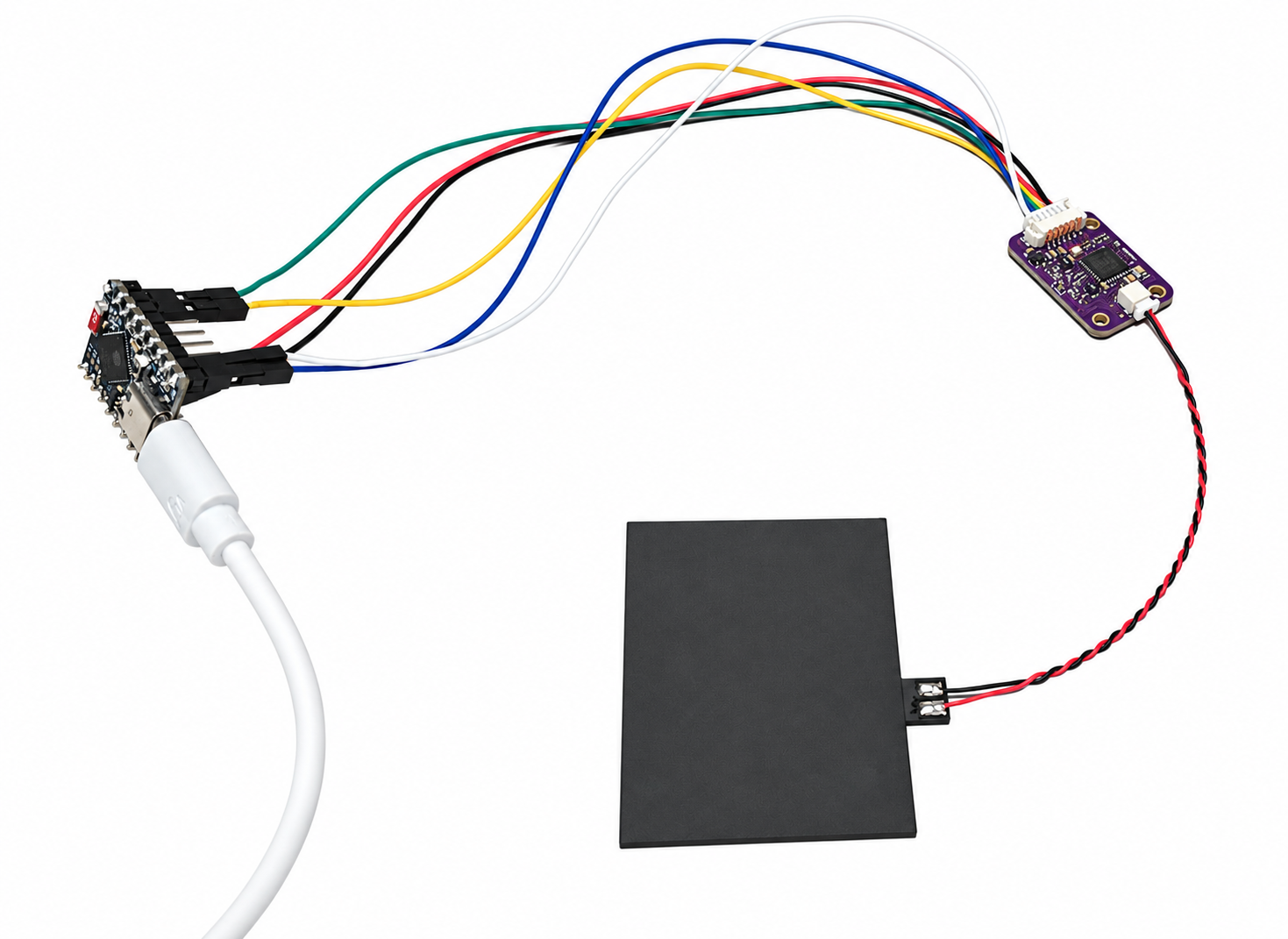
Disconnect power before wiring. Starting at the dot, the connector signals are SDA, SCL, IRQ, VEN, VCC, GND.
Connect by signal name, not wire color. The apparent left-to-right order is reversed when the mating plug is viewed from the opposite side. Align the keyed connector housing and do not force the plug.
Leave ADR0 and ADR1 open for the default 7-bit I2C address 0x28.
| Module pin | Signal | ESP32-S3 SuperMini |
|---|---|---|
| 1 | SDA | GPIO8 |
| 2 | SCL | GPIO9 |
| 3 | IRQ | GPIO4 |
| 4 | VEN | GPIO5 |
| 5 | VCC | 3V3 for this procedure |
| 6 | GND | GND |
Reserve at least 300 mA of supply capacity for the module; a 500 mA or higher-rated source provides additional margin. Budget the host board separately. Check that the development board's 3.3 V regulator can supply the combined load. SDA and SCL already have 4.7 kΩ pull-ups to 3.3 V.
3. Install the official library
- Download the ELECHOUSE library 3.1.3 ZIP used by this guide. The main library repository also provides updates and source code.
- In Arduino IDE, select Sketch → Include Library → Add .ZIP Library and select the downloaded ZIP.
- Open examples/DetectTags/DetectTags.ino, or select DetectTags from the library's examples menu.
- Save a working copy for your project, then make the configuration changes below.
This is the same software library linked from the standard ELECHOUSE PN7160 product. The ZIP is fixed to source revision a9c0f71 so the setup can be reproduced. Use this guide for the MINI's six-pin wiring and single VCC input. No separate MINI driver or NeoPixel library is required for DetectTags.
4. Configure DetectTags for the MINI
4.1 Set the pins and supply preset
Put this block at the top of your sketch, before the existing library #include lines. Remove any conflicting definitions in the sketch.
#define PN71XX_USE_SPI 0
#define PN71XX_I2C_SDA 8
#define PN71XX_I2C_SCL 9
#define PN71XX_I2C_IRQ 4
#define PN71XX_I2C_VEN 5
#define PN71XX_I2C_ADDR 0x28
#define PN71XX_I2C_CHIP_MODEL PN7160
#define PN71XX_FIXED_VBAT_3V3 1  // Module VCC = 3.3 V

#include <Wire.h>
// Keep the existing ELECHOUSE includes and the rest of DetectTags.
Keep the example's PN71XX_NFC_INSTANCE(nfc) and pn71xxConfigureExampleTransport(nfc) calls. They apply these settings. Explicit IRQ and VEN definitions are important because the shared example's generic ESP32-S3 defaults differ from this wiring.
| Module VCC | Sketch setting | Host signals |
|---|---|---|
| 3.3 V | #define PN71XX_FIXED_VBAT_3V3 1 | 3.3 V logic |
| 5.0 V | #define PN71XX_FIXED_VBAT_3V3 0 | 3.3 V logic; common ground |
The preset is not automatic voltage detection. For a 5 V design, connect module VCC to the 5 V supply and change the macro to 0; do not change the signal wiring to 5 V. Completely disconnect power before changing the wiring or supply preset, then upload the matching configuration.
4.2 Set the I2C clock
In setup(), add the following line after the initialization error-check block and before the first waiting-for-card message:
Wire.setClock(400000UL); // 400 kHz for normal operationThe library starts the I2C bus during initialization. Setting the clock after successful initialization makes the subsequent tag-reading traffic use 400 kHz. Reapply this line if your application closes and restarts the I2C bus.
5. Upload
- Select ESP32S3 Dev Module in Arduino IDE.
- For a board using the ESP32-S3 native USB connection, set USB CDC On Boot to Enabled.
- Select the board's serial port and upload the sketch.
- Open Serial Monitor at 115200 bit/s and reset the host board.
If your board needs manual download mode, hold BOOT, tap RESET, start the upload and release BOOT. Firmware is uploaded to the ESP32-S3; no programming connection to the NFC module is required for this procedure.
6. Verify NFC-A operation
- Confirm initialization completes and Serial Monitor displays a waiting-for-card message.
- Hold an NFC-A card close to and parallel with the antenna.
- Check the reported technology and NFC ID. DetectTags prints results to Serial Monitor; it does not provide the board-specific RGB LED indication.
- Remove the card and confirm that detection resumes.
For ISO15693 identifier handling, see the API notes. Card data and NDEF contents require the corresponding protocol example; detecting an identifier alone does not read protected application data.
| Symptom | First checks |
|---|---|
| No serial output | USB data cable, selected serial port, USB CDC setting and 115200 bit/s. |
| Initialization error | Connector orientation, VCC, common ground, GPIO overrides, address and IRQ/VEN connections. |
| Initializes but detects no card | One antenna connected, correct supply preset, card close to the antenna and no nearby metal. |