
TAIJI means TAICHI. TAIJIUINO Due board derives from Arduino Due. Compared with Arduino Due, we made some changes and improvement. But it is completely compatible with Arduino Due. Users could write code and program it in Arduino IDE.
The board contains everything needed to support the microcontroller; simply connect it to a computer with a micro-USB cable or power it with a AC-to-DC adapter or battery to get started. This board is compatible with all Arduino shields that work at 3.3V and are compliant with the 1.0 Arduino pinout.
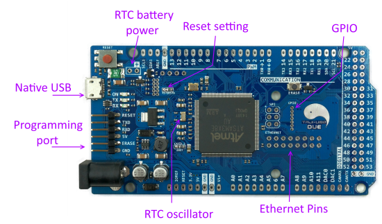
Exactly like Arduino, Taijiuino follows the 1.0 pinout:
- TWI: SDA and SCL pins that are near to the AREF pin.
- The IOREF pin which allows an attached shield with the proper configuration to adapt to the voltage provided by the board. This enables shield compatibility with a 3.3V board like the Due and AVR-based boards which operate at 5V.
- An unconnected pin, reserved for future use
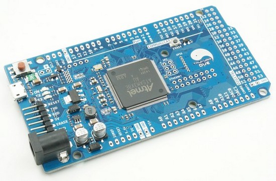
Taijiuino Due R2S is a simple version of Taijiuino Due R2. Female pins and male pins are not assembled on the board.
Compared with Arduino DUE
| Taijiuino R2S | Taijiuino R3S | |
|---|---|---|
| Difference Compared with Arduino Due | Add battery interface for RTC | |
| More RESET options: RSTB is connected to NRSTB RST is connected to NRST |
||
| Ethernet interface on the ATSAM3X8E microcontroller is now available on Taijiuino (Ethernet Module) | ||
| RTC battery assembled | ||
| Remove Programming USB Port and break out programming pins for external programmer (External Programmer) | ||
| 20 more pins available than Arduino DUE | ||
| Remove LED on P13 | ||
| Both 3.3V and 5V serial interface is available | ||
(Taijuino Due R3S picture)
Ethernet
ATmel ATSAM3X-EK has the same family ARM chip with Arduino Due. And AVR studio already has complete library for TCP/IP protocol. It is a pity that those pins for Ethernet are not available on Arduino Due. That’s what persuaded us to design a different board. In fact, developers are already developing Ethernet library for Arduino Due. Please visit this page: Connecting an Ethernet PHY to Arduino Due
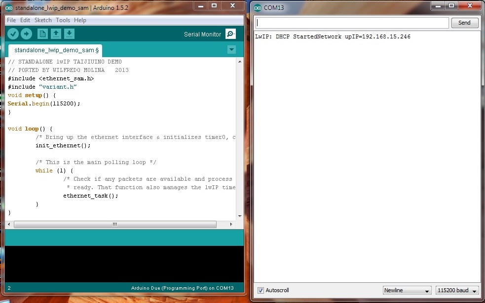
The following picture shows a webpage in Taijiuino.
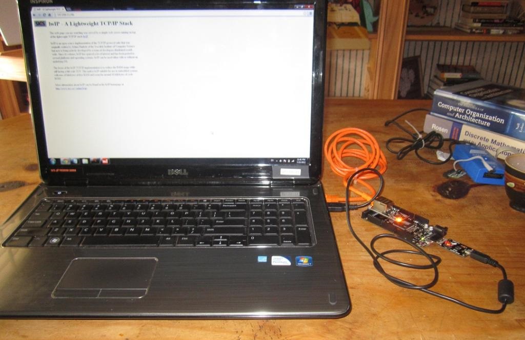
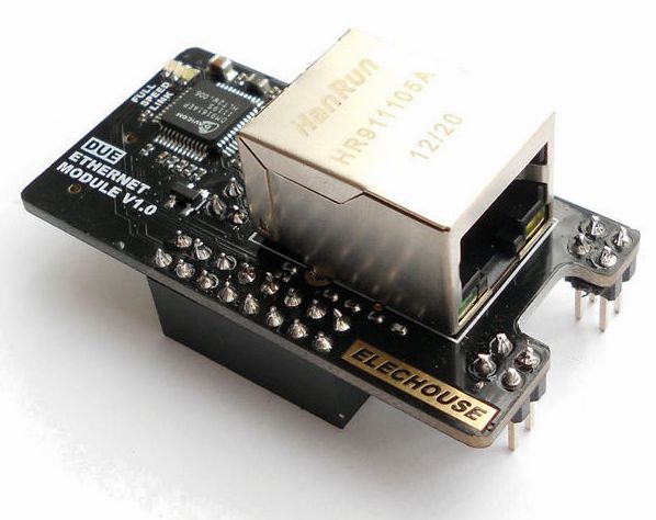
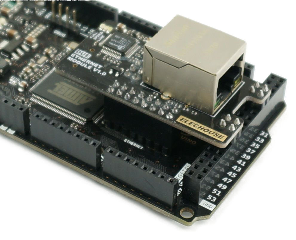
To connect with Taijiuino Due in to Ethernet network, an Ethernet PHY module is needed. We’ve already made one for Taijiuino. Users only need to plug in an play:
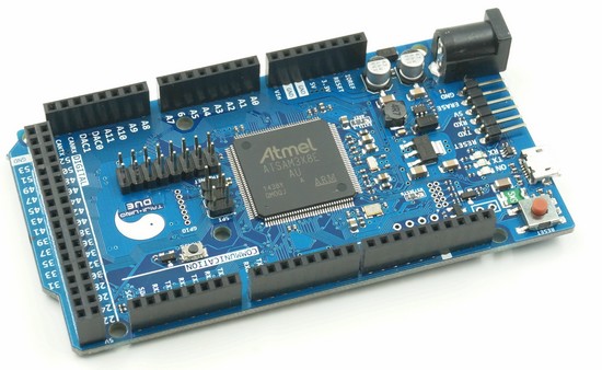
(Taijuino Due R2 picture)
Please note that currently the Ethernet library for Arduino DUE is still in developing by the 3rd party. If you are not capable to develop the library, temporarily you may don’t need this module.
For more information, please refer to the following links:
- Ethernet PHY module
- Unfinished library page (not developers’ official page)
Remove Programming USB Port
Users could program Arduino Due through either of the 2 USB port: Native USB, Programming USB.
On Taijiuino Due board, We removed Programming USB for the following reason:
- Save space for Ethernet Pins
- Users could program the board through Native USB port
- If necessary, users could choose external program downloaders.
Taijiuino Due has pins for external program downloaders. Those pins include 5V TTL UART port. It could invoke more innovation to programming methods. For example, it makes the following possible: programming wirelessly, programming offline.
External program downloader is more cost-efficient. Similar with boards such as Arduino Mini or Arduino Pro, many boards could share one external program downloaders.
We’ve already developed 2 kinds of program downloaders:
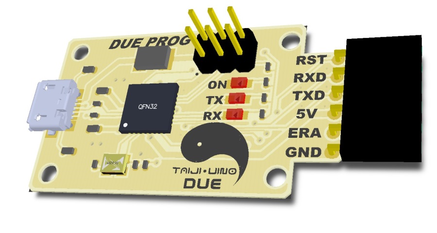
External Program Downloader (DUE_PROG)
We designed this downloader for Taijiuino. It is plug and play.
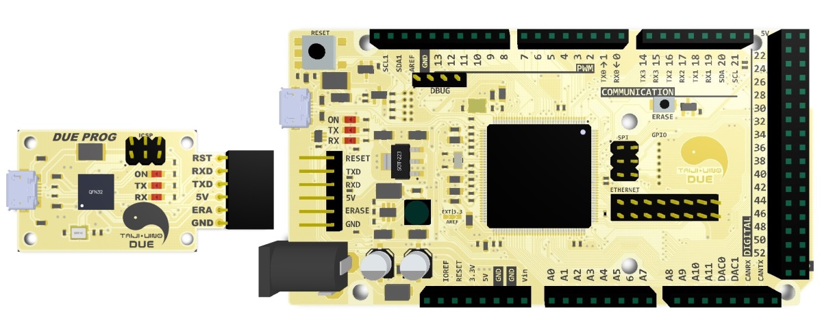
(Taijuino Due R2 picture)
This downloader is designed based on the ATmega16U2. With the bended-pin female header, users could plug in the header to Taijiuino Due board. In fact, this downloader module could program any Arduino board. And it also could serves as USB-TTL module.
You could get more information about it from this page.
It works like USB Serial Light Adapter.
DUE WIRELESS PROG
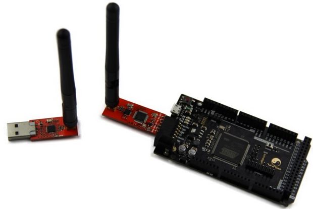
(Taijuino Due R2 picture)
You could get this product from Wireless program Downloader
This module could program the Taijiuino board wirelessly or send data between Taijiuino and PC wirelessly.
More pins
The chip ATSAM3X8E has several pins which are not available on Arduino. However, on Taijiuino Due, users could access those pins.
| Due Pin Number | SAM3X Pin Name | Mapped Pin Name |
|---|---|---|
| 78 | PB23 | TP1 |
| 92 | PB0 | ETXCLK |
| 93 | PB1 | ETXEN |
| 94 | PB2 | ETXD0 |
| 95 | PB3 | ETXD1> |
| 96 | PB4 | ERXDV |
| 97 | PB5 | ERXD0 |
| 98 | PB5 | ERXD1 |
| 99 | PB7 | ERXER |
| 100 | PB8 | EMDC |
| 101 | PB9 | EMDIO |
| 102 | PB10 | EXINT |
| 103 | PB24 | TP0 |
| 104 | PB23 | TP1 |
| 105 | PB22 | TP2 |
| 106 | PC27 | TP3 |
| 107 | PC20 | TP4 |
| 108 | PC10 | TP5 |
| 109 | PC11 | TP6 |
User could control those pins just as other Arduino pins:
// All this three lines do the same thing
pinMode(PB23, OUTPUT);
pinMode(103, OUTPUT);
pinMode(TP0, OUTPUT);
// All this three lines do the same thing
digitalWrite(PB23, HIGH);
digitalWrite(103, HIGH);
digitalWrite(TP0, HIGH);
For more information, please refer to our Github page.
Remove the led to pin 13
Led on Pin 13 might be helpful sometimes. We found that both PC30 and PA23 connected with LEDs. Users could use those 2 leds instead of led on Pin 13. So we remove the led on pin 13 to keep the board more simple.
In fact, for Arduino Due or Taijiuino Due, the leds are connected to Pin 72 and Pin 73. You could refer to this page to learn how to control the 2 leds.
Technique Detail
Warning: same with Arduino Due, Taijiuino Due runs at 3.3V. The maximum voltage that the I/O pins can tolerate is 3.3V. Providing higher voltages, like 5V to an I/O pin may damage the board.
ARM Core benefits
The Due has a 32-bit ARM core that can outperform typical 8-bit microcontroller boards. The most significant differences are:
- A 32-bit core, that allows operations on 4 bytes wide data within a single CPU clock. (for more information look int type page).
- CPU Clock at 84Mhz.
- 96 KBytes of SRAM.
- 512 KBytes of Flash memory for code.
- a DMA controller, that can relieve the CPU from doing memory intensive tasks.
Summary
| Microcontroller | AT91SAM3X8E |
| Operating Voltage | 3.3V |
| Input Voltage (recommended) | 7-12V |
| Input Voltage (limits) | 6-20V |
| Digital I/O Pins | 54 (of which 12 provide PWM output) |
| Analog Input Pins | 12 |
| Analog Outputs Pins | 2 (DAC) |
| Total DC Output Current on all I/O lines | 130 mA |
| DC Current for 3.3V Pin | 800 mA |
| DC Current for 5V Pin | 800 mA |
| Flash Memory | 512 KB all available for the user applications |
| SRAM | 96 KB (two banks: 64KB and 32KB) |
| Clock Speed | 84 MHz |
Power
The TAIJIUINO Due Pro can be powered via the USB connector or with an external power supply. The power source is selected automatically.
External (non-USB) power can come either from an AC-to-DC adapter (wall-wart) or battery. The adapter can be connected by plugging a 2.1mm center-positive plug into the board’s power jack. Leads from a battery can be inserted in the Gnd and Vin pin headers of the POWER connector.
The board can operate on an external supply of 6 to 24 volts. If supplied with less than 7V, however, the 5V pin may supply less than five volts and the board may be unstable. If using more than 12V, the voltage regulator may overheat and damage the board. The recommended range is 7 to 12 volts.
The power pins are as follows:
- VIN. The input voltage to the TAIJIUINO board when it’s using an external power source (as opposed to 5 volts from the USB connection or other regulated power source). You can supply voltage through this pin, or if supplying voltage via the power jack, access it through this pin.
- 5V. This pin outputs a regulated 5V from the regulator on the board. The board can be supplied with power either from the DC power jack (7 – 12V), the USB connector (5V), or the VIN pin of the board (7-12V). Supplying voltage via the 5V or 3.3V pins bypasses the regulator, and can damage your board. We don’t advise it.
- 3.3V. A 3.3 volt supply generated by the on-board regulator. Maximum current draw is 800 mA. This regulator also provides the power supply to the SAM3X microcontroller.
- GND. Ground pins.
- IOREF. This pin on the TAIJIUINO board provides the voltage reference with which the microcontroller operates. A properly configured shield can read the IOREF pin voltage and select the appropriate power source or enable voltage translators on the outputs for working with the 5V or 3.3V.
Memory
The SAM3X has 512 KB (2 blocks of 256 KB) of flash memory for storing code. The bootloader is preburned in factory from Atmel and is stored in a dedicated ROM memory. The available SRAM is 96 KB in two contiguous bank of 64 KB and 32 KB. All the available memory (Flash, RAM and ROM) can be accessed directly as a flat addressing space.
It is possible to erase the Flash memory of the SAM3X with the onboard erase button. This will remove the currently loaded sketch from the MCU. To erase, press and hold the Erase button for a few seconds while the board is powered.
Input and Output
- Digital I/O: pins from 0 to 53
Each of the 54 digital pins on the Due can be used as an input or output, using pinMode(), digitalWrite(), and digitalRead() functions. They operate at 3.3 volts. Each pin can provide (source) a current of 3 mA or 15 mA, depending on the pin, or receive (sink) a current of 6 mA or 9 mA, depending on the pin. They also have an internal pull-up resistor (disconnected by default) of 100 KOhm. In addition, some pins have specialized functions: - Serial: 0 (RX) and 1 (TX)
- Serial 1: 19 (RX) and 18 (TX)
- Serial 2: 17 (RX) and 16 (TX)
- Serial 3: 15 (RX) and 14 (TX)
Used to receive (RX) and transmit (TX) TTL serial data (with 3.3 V level). - PWM: Pins 2 to 13
Provide 8-bit PWM output with the analogWrite() function. the resolution of the PWM can be changed with the analogWriteResolution() function. - SPI: SPI header (ICSP header on other Arduino boards)
These pins support SPI communication using the SPI library. The SPI pins are broken out on the central 6-pin header, which is physically compatible with the Uno, Leonardo and Mega2560. The SPI header can be used only to communicate with other SPI devices, not for programming the SAM3X with the In-Circuit-Serial-Programming technique. The SPI of the Due has also advanced features that can be used with the Extended SPI methods for Due. - CAN: CANRX and CANTX
These pins support the CAN communication protocol but are not not yet supported by Arduino APIs. - TWI 1: 20 (SDA) and 21 (SCL)
- TWI 2: SDA1 and SCL1.
Support TWI communication using the Wire library. - Analog Inputs: pins from A0 to A11
The Due has 12 analog inputs, each of which can provide 12 bits of resolution (i.e. 4096 different values). By default, the resolution of the readings is set at 10 bits, for compatibility with other Arduino boards. It is possible to change the resolution of the ADC withanalogReadResolution(). The Due’s analog inputs pins measure from ground to a maximum value of 3.3V. Applying more then 3.3V on the Due’s pins will damage the SAM3X chip. The analogReference() function is ignored on the Due.
The AREF pin is connected to the SAM3X analog reference pin through a resistor bridge. To use the AREF pin, resistorBR1 must be desoldered from the PCB.
- DAC1 and DAC2
These pins provides true analog outputs with 12-bits resolution (4096 levels) with the analogWrite() function. These pins can be used to create an audio output using the Audio library.
Other pins on the board:
- AREF
Reference voltage for the analog inputs. Used with analogReference(). - Reset
Bring this line LOW to reset the microcontroller. Typically used to add a reset button to shields which block the one on the board.
Special pins on Taijiuino Due (Compared with Arduino):
- Digital I/O: pins from103 to 109
To use those pins as other pins on Arduino, we need to make some change to Arduino IDE. Please refer to this instruction. After finish the modification, each of the 7 digital pins on the Due can be used as an input or output, using pinMode(), digitalWrite(), and digitalRead() functions. They operate at 3.3 volts. Each pin can provide (source) a current of 3 mA or 15 mA, depending on the pin, or receive (sink) a current of 6 mA or 9 mA, depending on the pin. They also have an internal pull-up resistor (disconnected by default) of 100 KOhm.
- Ethernet Pins: pins from 92 to 102
Connect those pins to an Ethernet PHY module and Taijiuino could access networks. Those pins could also be used as an input or output, using pinMode(), digitalWrite(), and digitalRead() functions.
Communication
The Taijiuino Due Pro has a number of facilities for communicating with a computer, another Arduino or other microcontrollers, and different devices like phones, tablets, cameras and so on. The SAM3X provides one hardware UART and three hardware USARTs for TTL (3.3V) serial communication.
The programming pins are broken out for external program downloaders. Among those pins, the TXD and RXD pins are 5V TTL UART port, which are connect to TX0 and RX0 pins on Taijiuino Due through a 5V-3V3 TTL shifter.
The Native USB port is connected to the SAM3X. It allows for serial (CDC) communication over USB. This provides a serial connection to the Serial Monitor or other applications on your computer. It also enables the Due to emulate a USB mouse or keyboard to an attached computer. To use these features, see the Mouse and Keyboard library reference pages.
The Native USB port can also act as a USB host for connected peripherals such as mice, keyboards, and smartphones. To use these features, see the USBHost reference pages.
The Native USB port can also be used as a virtual serial port. Instead of using “Serial” object, use the “SerialUSB” object in the Arduino programming language, for example, SerialUSB.read()
The SAM3X also supports TWI and SPI communication. The Arduino software includes a Wire library to simplify use of the TWI bus; see the documentation for details. For SPI communication, use the SPI library.
Programming
The TAIJIUINO Due Pro can be programmed with the Arduino software (download). For details, see the reference and tutorials.
Uploading sketches to the SAM3X is different than the AVR microcontrollers found in other Arduino boards because the flash memory needs to be erased before being re-programmed. Upload to the chip is managed by ROM on theSAM3X, which is run only when the chip’s flash memory is empty.
There are two ways to program the boards:
- Native port: to use this port, select “TAIJIUINO Due Pro (Native USB Port)” as your board in the Arduino IDE. The Native USB port is connected directly to the SAM3X. Connect the Due’s Native USB port (the one closest to the reset button) to your computer. Opening and closing the Native port at 1200bps triggers a ‘soft erase’ procedure: the flash memory is erased and the board is restarted with the bootloader. If the MCU crashed for some reason it is likely that the soft erase procedure won’t work as this procedure happens entirely in software on the SAM3X. Opening and closing the native port at a different baudrate will not reset the SAM3X.
- External Programming port: to use this port, you need external program downloader. Now the DUE PROG downloader is available. Insert downloader to Taijiuino Due and then connect it with PC with an USB cable. PC would recognize the device as “Arduino Due”.For the first time, Windows OS requires driver. Please install in the following way:
- Plug in your board and wait for Windows to begin it’s driver installation process. After a few moments, the process will fail, despite its best efforts.
- Click on the Start Menu, and open up the Control Panel.
- While in the Control Panel, navigate to System and Security. Next, click on System. Once the System window is up, open the Device Manager.
- Look under Ports (COM & LPT). You should see an open port named “Arduino Due (COMxx)”
- Right click on the “Arduino Due (COMxx)” port and choose the “Update Driver Software” option.
- Next, choose the “Browse my computer for Driver software” option.
- Finally, navigate to and select the Due’s driver file, named “Arduino Due Programming Port.inf”, located in the “Drivers” folder of the Arduino Software download (not the “FTDI USB Drivers” sub-directory).
- Windows will finish up the driver installation from there.
In Arduino IDE, choose
- Tools -> Board -> Arduino Due (Programming Port)
- Tools -> Serial Port -> COMXX
Then program it and play.
USB Overcurrent Protection
The TAIJIUINO Due has a resettable polyfuse that protects your computer’s USB ports from shorts and overcurrent. Although most computers provide their own internal protection, the fuse provides an extra layer of protection. If more than 500 mA is applied to the USB port, the fuse will automatically break the connection until the short or overload is removed.
Schematic, Reference Design & Pin Mapping
Visit our Github page to download schematic and Gerber file
Product List
Taijiuino Due R3S x1