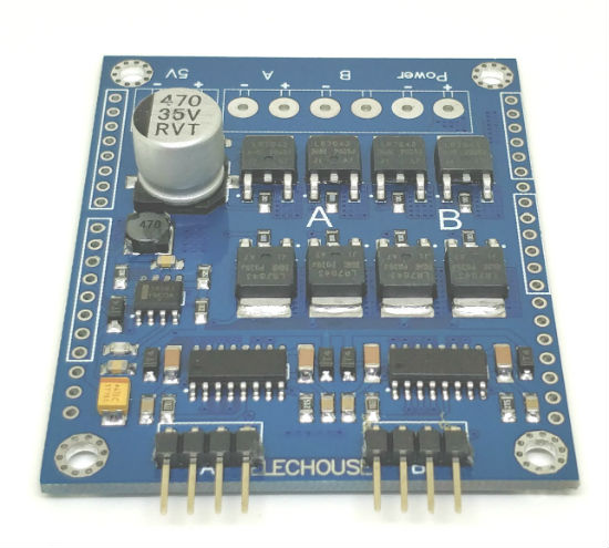
This motor driver works with single channel max 20A working current capacity. This module performs far better than MC33886 or L298 motor driver, especially in terms of motor speed control and power efficiency.
This driver has a brake function, which can quickly stop the motor. And the operation is very easy.The driver module contains a full-bridge driver chip and MOSFET with as low as 0.003 Ohm internal resistance. The full-bridge driver IC minimizes the switching loss of MOSFET and improves power efficiency.
This driver module can work under the PWM duty cycle of 0% -98%.
Parameter
- Peak current (Load): 150A
- Recommend max working current(Load): 20A
- Power VCC (Load): 0V~30V
- Recommend power VCC (load) : 12V ~ 26V
- Controlling VCC: 4V~12V
- Controlling TTL Voltage; 2.5V ~ 12V
Note:
- Controlling TTL voltage means the High voltage of the control pins (EN, LPWM, RPWM, DIS).
- The stable max working current is 20A while load VCC is between 12V~30V. The current is restricted by heat dissipation. Current, we don’t add any heat radiator on the board.So if the current is over 20A, the heat may melt the sldering tin and cause problems. If you want it working stable at higher current, you should add radiator.
- Power VCC is recommended to be higher than 12V if your load is large-current devices. While over 12V, the MOSFET is working fully and its power consumption is small. So the heat will be less. If your load current is not large and just several Amperes, the power VCC can be as low as 3V.
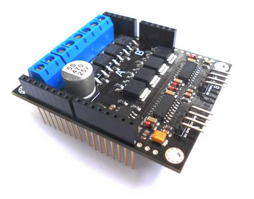
Interface
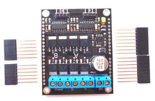
We are trying to let this driver be compatible with Arduino and non-Arduino users. We leave holes on the PCB and so mount long-pin felmale hearders to plug in Arduino. If you are non-Arduino user, leave the holes alone.
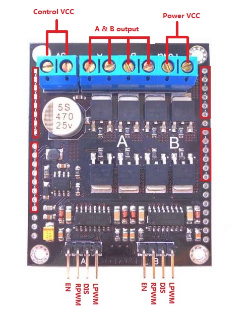
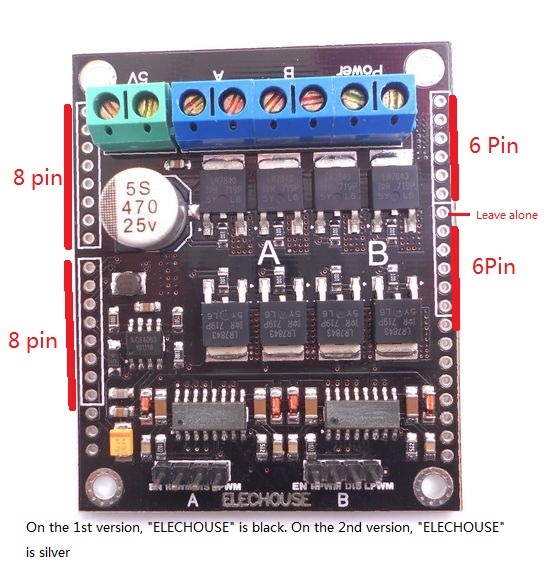
Pins above in the red box are for Arduino. They are for Arduino.
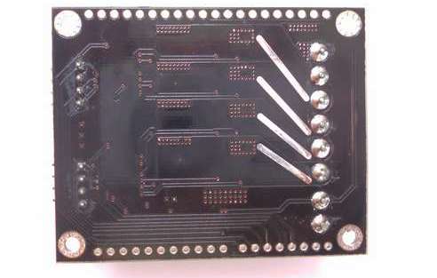
To improve performance while with large current load. you could add soldering tin on the routs shown below.
Dimension
- PCB Size: 52.3mm x 63.9mm
- Mount Hole: 44.4mm x 57.0mm, 3mm Diameter
- High: 12.4mm (without long-pin headers) or 27.4mm (with long-pin headers)
Control
Basically the control is very easy.
- Rotate forward: EN = HIGH, RPWM = PWM, LPWM = HIGH, DIS = vacant
- Rotate reverse: EN = HIGH, RPWM = HIGH, LPWM = PWM, DIS = vacant
- Stop and brake: EN = HIGH, RPWM = HIGH, LPWM = HIGH, DIS = vacant
- Stop but not brake: EN = 0, RPWM = HIGH, LPWM = HIGH, DIS = vacant
- Prohibit : EN = X, RPWM = X, LPWM = X, DIS = HIGH
For Arduin users:
|
Channel
|
Driver Module
|
Arduino Pin (V1)
|
Arduino Pin (V2) |
|
A
|
EN
|
2
|
2
|
|
RPWM
|
3
|
3
|
|
|
DIS
|
4
|
4
|
|
|
LPWM
|
5
|
11
|
|
|
B
|
EN
|
8
|
8
|
|
RPWM
|
9
|
9
|
|
|
DIS
|
7
|
7
|
|
|
LPWM
|
6
|
10
|
Please note:
- Smaller PWM duty will get higher speed.
- PWM frequency should be 1Khz ~ 60Khz. Smaller frequency could get it work but not in perfect performace.It may increase the module’s response time, but very slight in nanosecond level.We are not able to sense it. Default frequency of Arduino PWM is 0.5Khz. In our test, the default frequency could get it work very well. But remember, for better performance, the recommended frequency is 1Khz ~ 60Khz. In our library, we set the pwm frequency over 1Khz.
Note
The software is also modified for version 2. You could find corresponding comments on the change in the library.
Document
Product list
- 50A motor drive module x1