Library update: The SPI compatibility issue has been resolved in the official ELECHOUSE library. The shared examples in ELECHOUSE_PN7150_PN7160 (GitHub) can be used with PN7161 MINI V1 SPI after enabling SPI mode and selecting the 3.3 V or 5 V power preset that matches VANT.
PN7161 MINI NFC Module (SPI)
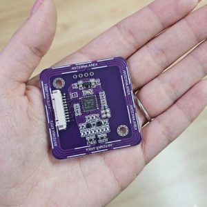
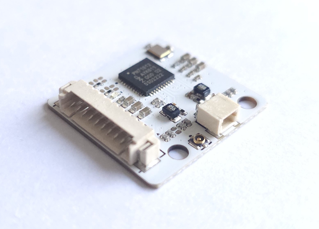
The PN7161 MINI V1 — SPI is the SPI member of the PN7161 family from ELECHOUSE. It is intended for embedded systems that require an SPI interface, especially compact boards, Linux-based controllers, Raspberry Pi, and ESP32 designs.
If you need the PN7161 feature set on an SPI-based design, this is the correct module. If your system is built around I2C, use the PN7161 NFC RFID Module (I2C).
Why Choose PN7161 MINI SPI
- SPI interface for platforms that do not use I2C as the main NFC bus
- Compact form factor for space-constrained embedded products
- Part of the PN7161 family, including Apple ECP support
- Suitable for Raspberry Pi, ESP32, Linux, and custom controller boards
Key Specifications
| Chip | NXP PN7161 |
|---|---|
| Interface | SPI |
| Protocol Stack | NCI 2.0 |
| Apple ECP | Supported |
| Logic Supply (VDD) | 3.3 V for the documented ESP32 workflow |
| RF Supply (VANT) | 3.3 V or 5 V; software preset must match |
| Board Style | Compact MINI format |
Antenna and Reading Distance
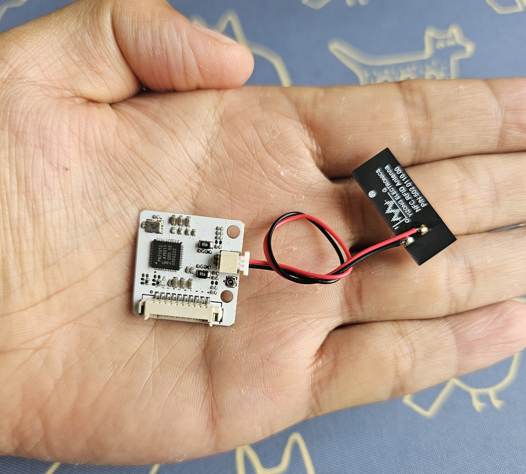
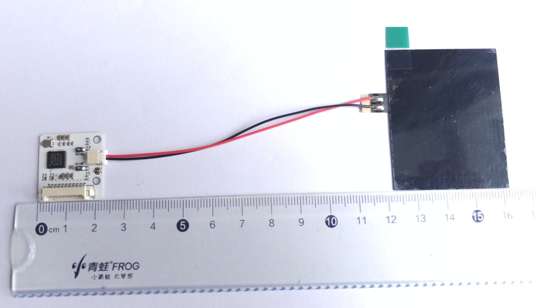
The PN7161 MINI V1 — SPI uses flexible external NFC antennas. The package includes both antenna sizes listed below: one 40 mm × 50 mm antenna and one 10 mm × 25 mm antenna. They are included together, not selected as alternative sizes. Reading distance depends on antenna size, ferrite backing, tag size, tag orientation, power supply, and the surrounding installation environment.
Antenna and Mechanical Details
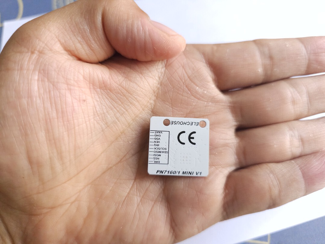
| Main board size | 22.6 mm × 23.5 mm × 4.4 mm |
|---|---|
| Antenna size options | 40 mm × 50 mm × 0.2 mm; 10 mm × 25 mm × 0.2 mm |
| Included antennas | Both 40 mm × 50 mm and 10 mm × 25 mm flexible antennas are included with the module. |
| Ferrite backing | The standard shipped antennas are without ferrite. Ferrite-backed antennas are customized versions and should be requested before ordering. |
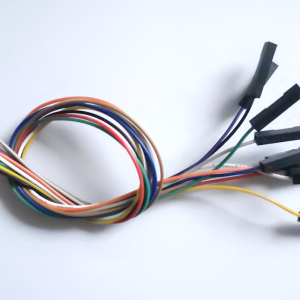
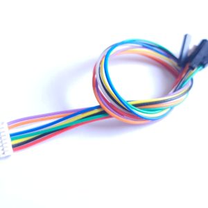
| Connection cable | 10 cm |
| Antenna connectors | IPEX and SH1.0 interfaces supported |
| Antenna features | Thin and flexible antenna; custom antenna sizes available for project requirements |
Reading Distance Test Results
| Antenna configuration | Square Mifare S50 card (85 mm × 54 mm) |
Round Mifare S50 tag (25 mm diameter) |
Note |
|---|---|---|---|
| 40 mm × 50 mm antenna without ferrite | 10 cm | 4.8 cm | Standard shipped version (included by default) |
| 40 mm × 50 mm antenna with ferrite | 5.8 cm | 3.3 cm | Customized version (available on request) |
| 10 mm × 25 mm antenna without ferrite | 4.2 cm | 2.3 cm | Standard shipped version (included by default) |
| 10 mm × 25 mm antenna with ferrite | 3.0 cm | 2.0 cm | Customized version (available on request) |
Test note: In the table above, Standard shipped version means the default antennas included with the product. Customized version means a ferrite-backed/custom antenna version that should be requested before ordering. The values are typical test results; actual reading distance may vary with card/tag type, antenna orientation, mounting material, nearby metal, cable routing, and RF interference.
Apple integration boundary: PN7161 provides the related ECP reader hardware capability. Apple Wallet / Apple VAS authorization, certification, credentials, and application software remain the customer’s responsibility.
Reading-distance test condition: the published antenna results above were measured in the existing VANT=5 V RF-supply test configuration. They are not 3.3 V performance data and do not claim identical range between the two supply modes.
Supported NFC Functions
- Reader / Writer
- Peer-to-Peer
- Card Emulation
- ISO 14443A / 14443B
- ISO 15693
- MIFARE and FeliCa
Typical Applications
- Compact NFC reader devices
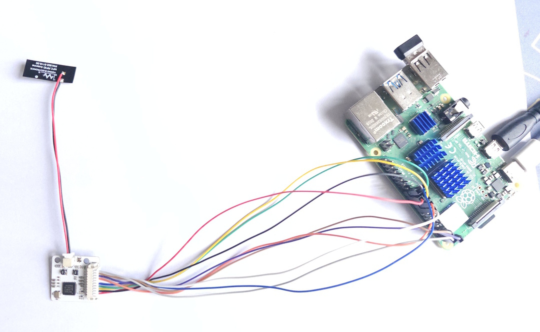
- SPI-based Raspberry Pi and Linux projects
- ESP32 and embedded controller integration
- Industrial and custom embedded NFC products
PN7161 MINI SPI to ESP32 VSPI Typical Wiring
| PN7161 MINI SPI | ESP32 Dev Module | Notes |
|---|---|---|
| SCK | GPIO18 | SPI clock |
| MISO | GPIO19 | SPI MISO |
| MOSI | GPIO23 | SPI MOSI |
| SS / NSS | GPIO5 | Chip select |
| IRQ | GPIO14 | Interrupt |
| VEN | GPIO13 | Enable / reset |
| VDD | 3.3V | Logic supply |
| VANT | 3.3 V or 5 V | RF / antenna supply; select the matching software preset |
| GND | GND | Common ground |
RF Supply and SPI Library Configuration
VANT supports either 3.3 V or 5 V. Keep VDD at the host-I/O logic voltage (3.3 V for the ESP32 examples), and never connect 5 V to VDD. The VANT voltage and software power preset must match; there is no automatic voltage detection. Verify that the selected host or external VANT rail has enough current capacity for RF peaks.
| RF supply mode | Power wiring | Shared SPI example setting |
|---|---|---|
| 3.3 V RF supply | VDD=3.3 V, VANT=3.3 V, common GND | PN71XX_USE_SPI 1 and PN71XX_FIXED_VBAT_3V3 1. This is the current shared SPI example default. |
| 5 V RF supply | VDD=3.3 V, VANT=5 V, common GND | PN71XX_USE_SPI 1 and explicitly set PN71XX_FIXED_VBAT_3V3 0. |
Use ELECHOUSE library source version 3.1.2, commit 10a1cb2 or later. Define both macros before including Electroniccats_PN71xx_ExampleTransport.h:
#define PN71XX_USE_SPI 1
#define PN71XX_FIXED_VBAT_3V3 1  // 1 for 3.3 V VANT; 0 for 5 V VANT
These macros take effect through pn71xxConfigureExampleTransport(nfc). In a custom SPI sketch, explicitly selecting PN7160 makes the PN7161 compatibility path clear:
Electroniccats_PN7150 nfc(IRQ_PIN, VEN_PIN, SS_PIN,
                          SCK_PIN, MISO_PIN, MOSI_PIN,
                          PN7160, &SPI);
A custom sketch that does not use the shared helper must also call the setter directly. For manual initialization, call connectNCI(), select the matching preset with setPn7160FixedVbat3V3(...), and then call configureSettings(). Because begin() calls configureSettings() internally, select the preset before calling begin() when using that shortcut path. Power down before changing VANT or its preset.
Arduino / Linux distinction: the setter, macros, and shared helper above configure only the ELECHOUSE Arduino/ESP32 library. They do not configure NXP’s Linux NFC stack. The copy-paste ELECHOUSE 3.3 V Linux procedure is still being validated; use a known-good 5 V Linux configuration for the exact middleware/module combination or contact ELECHOUSE support until that procedure is published.
Documentation and Test Guides
Product information stays on this page. Wiring, Raspberry Pi setup, ESP32 validation, and software test flows are maintained separately in the documentation hub.
Downloads
Package and Support
- 1 × PN7161 MINI V1 — SPI module
- 2 × flexible NFC antennas included: 40 mm × 50 mm and 10 mm × 25 mm
- Technical documents and validation references available in the documentation hub, including ELECHOUSE_PN7150_PN7160 (GitHub) for Arduino and ESP32 development
Arduino Library and Examples
- Use ELECHOUSE_PN7150_PN7160 (GitHub) for Arduino and ESP32 development
- The shared library
examples/now support PN7161 MINI V1 SPI directly - Set
PN71XX_USE_SPI 1in the example sketch. - For 3.3 V VANT, set
PN71XX_FIXED_VBAT_3V3 1. For 5 V VANT, explicitly set it to0; shared SPI examples otherwise default to the 3.3 V preset. - SPI examples use the PN7160-compatible path, which is the intended compatibility path for PN7161 in this library
Wiring Reminder
For the documented 3.3 V host workflow, connect VDD to 3.3 V and GND to GND. VANT may connect to 3.3 V or 5 V; set PN71XX_FIXED_VBAT_3V3 to 1 or 0 respectively.