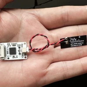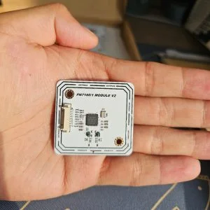
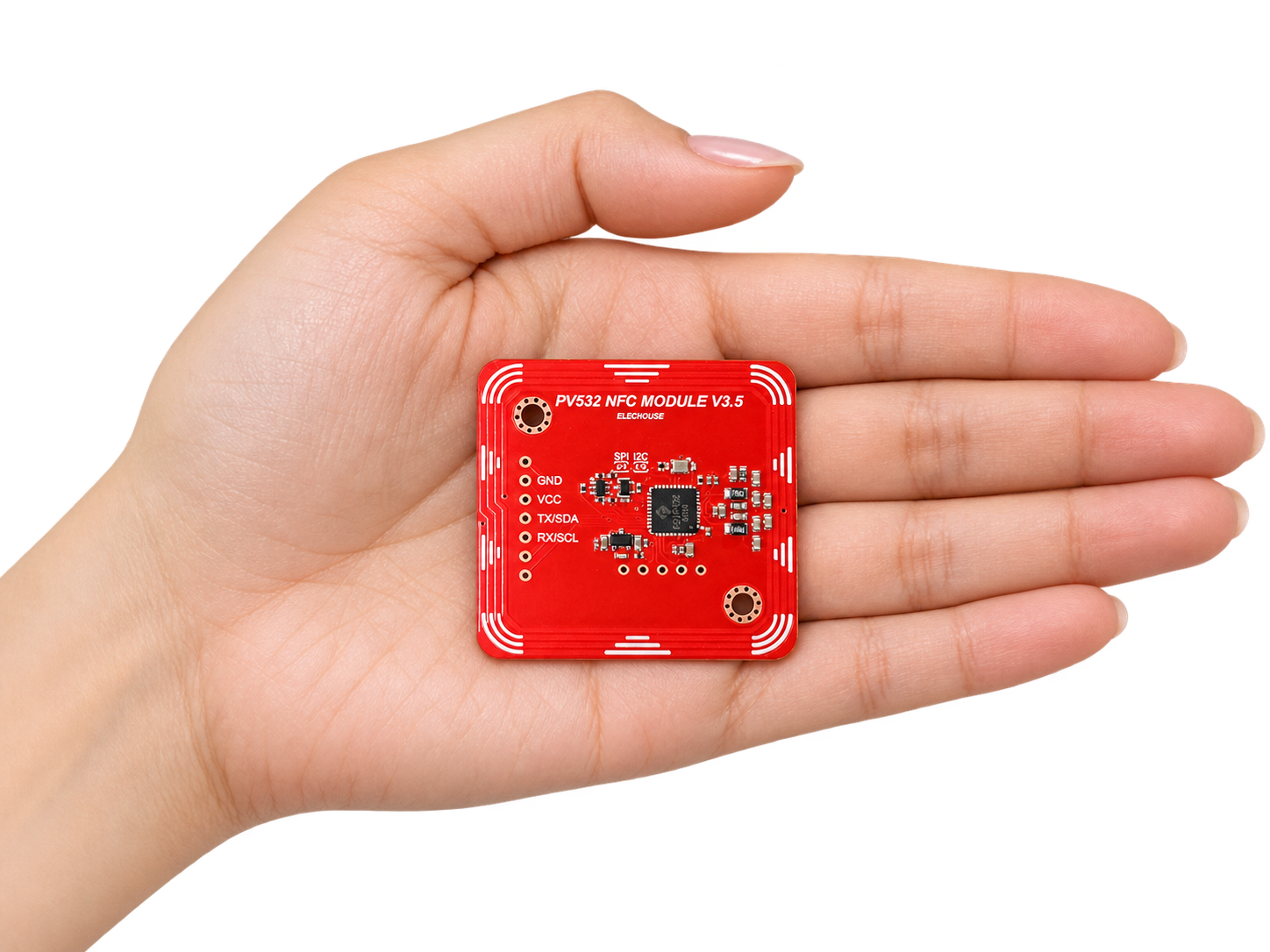
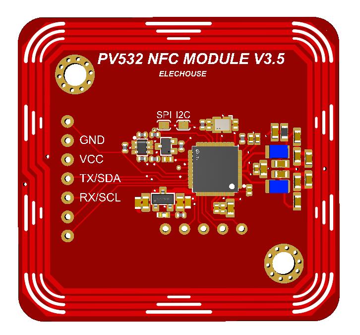
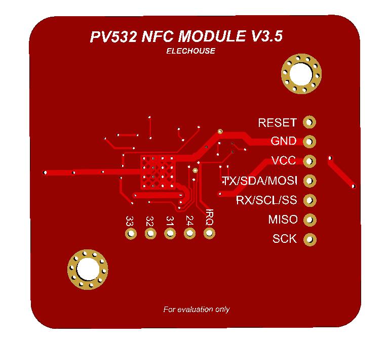
Designed for V4 mechanical and UART/I2C interface compatibility: reuse the existing board footprint, mounting positions and main four-pin connector location. All PV532 V3.5 communication signals use 3.3 V logic.
Compatibility with V4
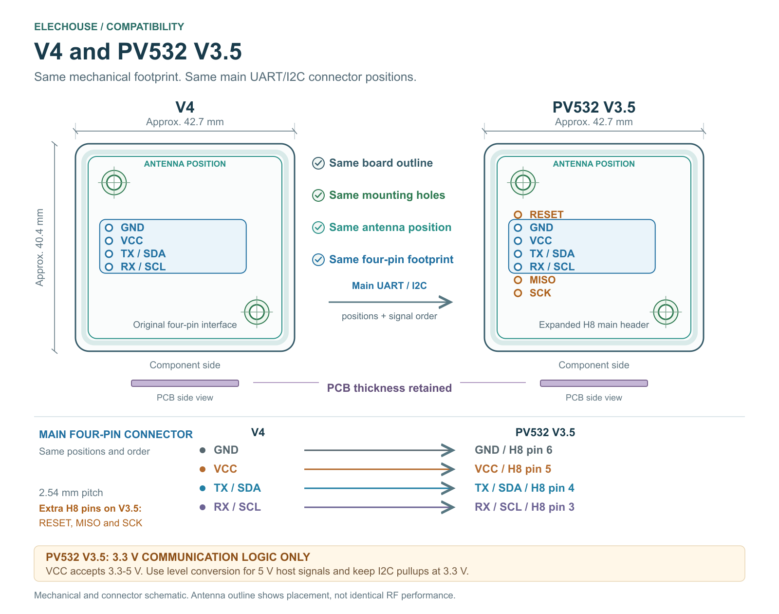
PV532 V3.5 retains the V4 board size, PCB thickness, mounting-hole positions and antenna position. The main four-pin UART/I2C interface keeps the same location and signal sequence, allowing existing mechanical designs and connector footprints to be reused.
| Compatibility item | PV532 V3.5 |
|---|---|
| Board size and shape | Fully compatible with V4; approximately 42.7 x 40.4 mm |
| PCB thickness | Compatible with V4 |
| Mounting holes | Same mounting-hole positions |
| Antenna position | Same antenna placement within the board footprint |
| Main UART/I2C interface | Same four-pin location and signal order; H8 pins 3-6 on PV532 V3.5 |
| Communication logic | 3.3 V on I2C, SPI and UART; review 5 V host signals and pullups |
| SPI and auxiliary connections | Use the PV532 V3.5 pin assignments in the manual |
Check the signal voltage when replacing V4. PV532 V3.5 uses 3.3 V logic even when VCC is supplied with 5 V. Use suitable level conversion for 5 V host outputs, and keep I2C pullups in the 3.3 V domain. SPI and auxiliary headers use the PV532 pin definitions in the manual.
Advantages Compared with V4
- More convenient SPI wiring: SPI signals are brought together on the expanded 2.54 mm main header, making host connections easier to access.
- 3.3 V power supply support: the module can be powered directly from a 3.3 V rail, while retaining support for a 5 V supply.
- RESET on the main interface: H8 pin 7 provides an active-low reset input for host-controlled reset and recovery.
Tradeoff Compared with V4
Communication interfaces support 3.3 V logic only. This applies to I2C, SPI and UART. A 5 V supply does not make the signal pins 5 V tolerant; 5 V host outputs require suitable level conversion.
Core Advantages
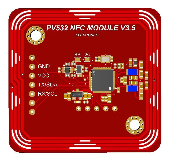
- V4-compatible board size, PCB thickness, mounting holes and antenna position.
- Same main four-pin UART/I2C connector location and signal order as V4.
- FSVP532 NFC controller, compatible with PN5321; module firmware version 1.6.
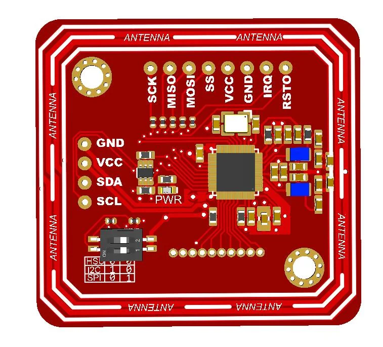
- Selectable I2C, SPI and HSU UART interfaces with 3.3 V logic.
- Accessible SPI signals and a RESET control pin on the expanded main header.
- 3.3 V to 5 V supply input and an integrated 13.56 MHz PCB antenna.
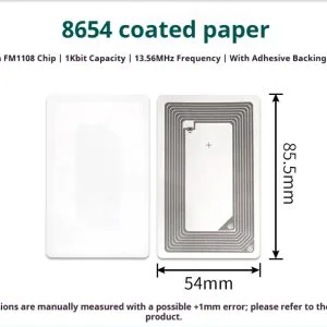
- Measured 75 mm reading distance with a 54 x 85.5 mm S70 card.
Key Specifications
| Parameter | Specification |
|---|---|
| Chip | FSVP532, compatible with PN5321 |
| Module firmware | Version 1.6 |
| Operating frequency | 13.56 MHz |
| Interfaces | I2C, SPI and HSU UART; select one at a time |
| Supply voltage | 3.3 V to 5 V DC |
| Logic level | 3.3 V for all communication interfaces |
| Antenna | Integrated PCB antenna |
| Board size | Approximately 42.7 x 40.4 mm |
| Measured reading distance | 75 mm with the tested S70 rectangular card (54 x 85.5 mm); see tag-specific results below |
Supported Protocols
- ISO14443A / MIFARE: Classic, Ultralight, DESFire and NTAG21x families.
- ISO14443B.
- FeliCa.
- ISO18092 NFCIP-1.
Tag memory access, authentication, NDEF, peer-to-peer operation and card emulation depend on the host software. The supplied ESP32 examples demonstrate firmware detection and ISO14443A UID reading.
Measured Reading Distance
Reading distances at 3.3 V and 5 V supply are nearly identical. One reference result is shown for each tested card or tag.
| Card type and shape | Measured reading distance (mm) |
|---|---|
| S70 – Rectangular (54 x 85.5 mm) | 75 |
| M1 – Circular (diameter 25 mm) | 40 |
| ISO14443B – Rectangular (54 x 85.5 mm) | 45 |
| NTAG215 – Rectangular (16 x 6 mm) | 20 |
| NTAG215 – Circular (diameter 25 mm) | 45 |
These are measured reference values. Actual distance depends on the tag antenna, orientation, enclosure and electrical environment.
Power Consumption Overview
Whole-module measurements show approximately 1.5 mA in software PowerDown, 13-14 mA with RF off, 25 mA during 2 Hz S70 reading, and 102-107 mA during continuous S70 reading.
The table summarizes measured mean current and input power. The ESP32-C3 host is excluded.
| Operating condition | Nominal 3.3 V (current / power) | Nominal 5 V (current / power) |
|---|---|---|
| PowerDown sleep | 1.57 mA / 5.21 mW | 1.51 mA / 7.66 mW |
| Ready with RF off | 13.82 mA / 45.19 mW | 13.16 mA / 66.56 mW |
| S70 read at 2 Hz | 25.33 mA / 80.97 mW | 25.27 mA / 126.18 mW |
| Continuous RF field | 82.06 mA / 262.92 mW | 87.57 mA / 432.03 mW |
| Continuous S70 read | 101.56 mA / 321.80 mW | 106.57 mA / 522.25 mW |
Supply labels are nominal; terminal voltage varied under load. See the user manual for the measured voltages, test conditions and detailed power data.
Typical Use Cases
- NFC tag identification and embedded automation.
- Access control and attendance system prototyping.
- Tag data and NDEF development with suitable software.
- NFC integration in existing V4 mechanical designs.
Frequently Asked Questions
Can I reuse a V4 enclosure and main connector?
Yes. Board size, PCB thickness, mounting-hole positions, antenna position and the main four-pin UART/I2C connector footprint are compatible with V4. Check the 3.3 V signal requirement before connecting an existing host.
Can I power the module from 5 V?
Yes. VCC accepts 3.3 V to 5 V DC. Communication signals remain at 3.3 V logic.
Which chip and firmware does it use?
The module uses FSVP532, compatible with PN5321, and firmware version 1.6.
Test Software
The updated PN5321 GitHub repository includes a standalone ESP32-C3 UART card-identification and manual range-test program. It provides automatic or fixed-protocol scanning, sample labels, manually entered distances, 20-attempt statistics and CSV result lines.
The program includes Type A, Type B, FeliCa, Jewel/Topaz and a dedicated ST SR-family entry. Identification, authenticated reads and Type 2 version queries use separate test criteria. It does not write card data. See the range-test guide for the reference GPIO4/5 wiring, commands and current validation scope. Distance is measured manually.
This standalone test needs no external NFC library. The basic classic ESP32 UART/I2C/SPI UID examples remain available as a separate example set.
Download
- User Manual (PDF)
- Latest Test Software (GitHub)
- ESP32-C3 Range-Test Guide (English)
- 3D Model (STEP in ZIP)
Product List
- PV532 NFC RFID Module V3.5 x 1